
Article
Taking Mitsubishi Mini-Splits Local with CN105
How I built two local, bidirectional ESPHome controllers for Mitsubishi MSZ-FH12NA mini-splits—and discovered 12.48 volts on a connector pin commonly documented as unused.
I like our Mitsubishi mini-splits. The official smart-control experience was another matter.
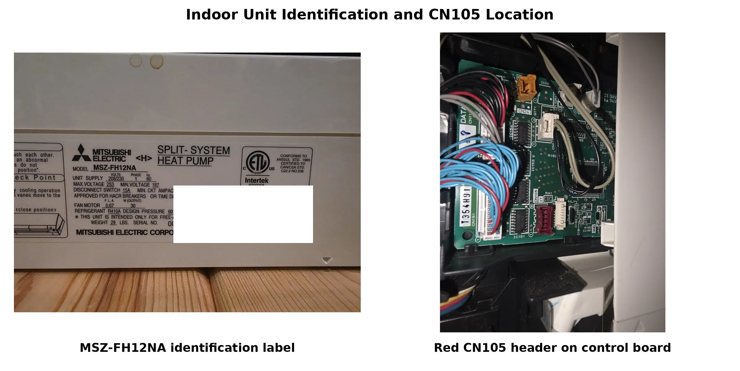
We have two Mitsubishi MSZ-FH12NA indoor heads at Frog Hill, one upstairs and one downstairs. They are quiet, effective, and generally excellent appliances. I wanted them in Home Assistant for the usual reasons: one place to control the house, better visibility when we are away, and eventually some carefully designed cold-weather monitoring.
The obvious first choice was Mitsubishi’s own kumo cloud system. I bought the official wireless-interface devices, installed them, and tried to pair them with the cloud service. Then I tried again. I researched the problem ad nauseam, checked the local network, repeated the setup process, and followed every useful lead I could find.
I never got them to connect and pair successfully.
Eventually I returned the devices.
That experience does not prove that every kumo cloud installation fails, but I was clearly not the only person who struggled with it. The Apple App Store review history and Google Play review history contain recurring complaints about pairing, connectivity, login, and reliability. Mitsubishi has since replaced kumo cloud with its newer Comfort app, describing the replacement as an improved experience with stronger connections and easier onboarding.
Perhaps the newer software is better. By then, however, I was much more interested in a local interface that I could understand, test, repair, and keep operating without depending on a vendor cloud.
The mini-splits deserved a better control path.
The problem with infrared control
Before this project, Home Assistant controlled both units through Broadlink infrared blasters and SmartIR climate entities.
That arrangement was useful, and I have retained it as a fallback. It also had a fundamental limitation: infrared control is mostly one-way.
Home Assistant
    -> SmartIR
    -> Broadlink IR blaster
    -> Mitsubishi mini-split
Home Assistant could transmit a complete remote-control state, but it did not receive authoritative state back from the appliance. If somebody used the physical Mitsubishi SG15H remote, Home Assistant could be left believing something different from what the mini-split was actually doing.
That is acceptable for a convenient remote control. It is not ideal for an operational system that may eventually matter while the house is unattended in winter.
What I wanted was direct, local, bidirectional communication:
Home Assistant
      |
      | ESPHome native API over local Wi-Fi
      v
M5Stack AtomS3 Lite
      |
      | UART through a level shifter
      v
Mitsubishi CN105
Finding CN105
Many Mitsubishi indoor units include a five-position service or accessory connector called CN105. It exposes power and a serial communication interface used by Mitsubishi accessories and third-party controller projects.
In April 2026, ESPHome added a native mitsubishi_cn105 climate component. Its component documentation describes local control and state reporting through the connector without requiring a custom external component or cloud service.
That made the project especially attractive. I could use a small ESP32-S3 controller, integrate it through ESPHome’s normal encrypted API, and keep the entire operational path on the Frog Hill network.
The basic hardware was modest:
- One M5Stack AtomS3 Lite for each indoor unit.
- A third AtomS3 Lite retained as a bench/reference controller.
- Five-wire CN105 pigtails.
- KeeYees four-channel 3.3-volt/5-volt bidirectional level shifters.
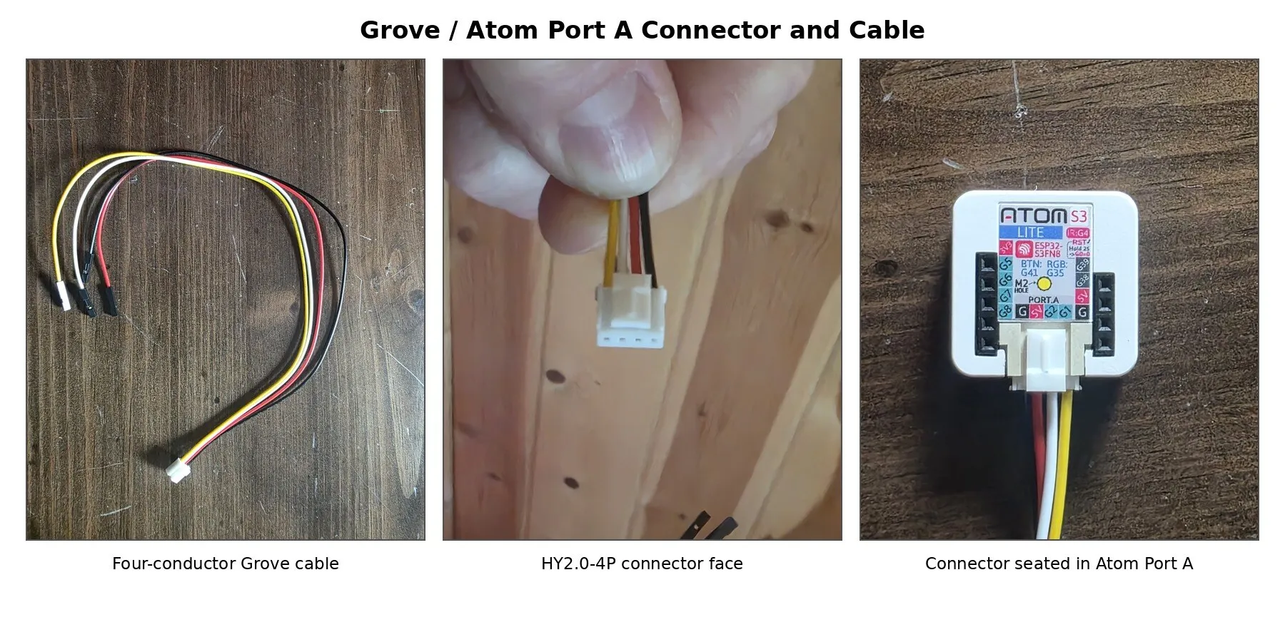
- Grove/HY2.0-4P cables for the production assemblies.
- Heat shrink, header pins, wire, and strain relief.
The important part was not buying the parts. It was refusing to assume that a generic CN105 diagram necessarily described the two appliances in front of me.
Measure first, connect later
The upstairs unit became the first test subject.
With the breaker off, I opened the indoor head, located the red five-position CN105 header, photographed its orientation, and continuity-mapped every conductor in the purchased pigtail.
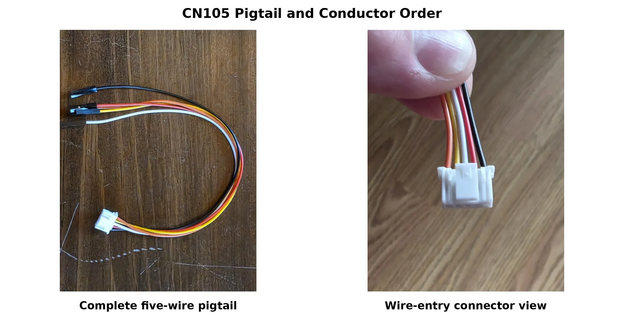
The pigtail’s conductor order was:
CN105 pin 1: black
CN105 pin 2: red
CN105 pin 3: white
CN105 pin 4: yellow
CN105 pin 5: orange
Those colors describe the particular pigtails I purchased. They should not be treated as a universal Mitsubishi color standard.
After restoring power, I measured each conductor relative to pin 2, which continuity and voltage checks confirmed as ground.
| CN105 pin | Pigtail color | Measured behavior |
|---|---|---|
| 1 | Black | 12.48 V steady |
| 2 | Red | Ground |
| 3 | White | 5.041 V steady |
| 4 | Yellow | Indoor-unit TX to controller RX |
| 5 | Orange | Indoor-unit RX from controller TX; approximately 4.9 V idle |
The first measurement was the most important result in the entire project.
ESPHome’s CN105 documentation currently shows pin 1 as unconnected, while also warning users to verify the real pinout and voltage levels before connecting anything. On both Frog Hill MSZ-FH12NA units, the black pin-1 conductor was not unconnected. It carried a steady 12.48 volts.
That conductor was individually insulated, secured, and left completely unused.
Had I treated the generic diagram as an instruction rather than a starting point, I could have applied 12.48 volts somewhere it did not belong. A 3.3-volt ESP32 is an unforgiving way to discover that an online pinout does not match the appliance on the bench.
Why I kept the level shifter
The AtomS3 Lite is a 3.3-volt device. The Mitsubishi side operates in a 5-volt domain, and the unit’s receive line idled close to 5 volts.
I therefore did not connect the UART lines directly.
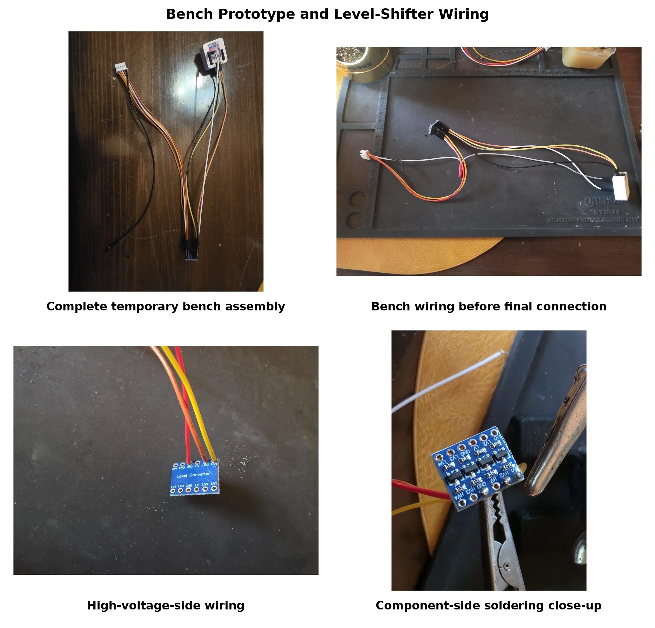
The available KeeYees boards are inexpensive passive MOSFET level shifters commonly sold for I²C use. They are not the first thing I would select for every push-pull UART design, so I treated one as an experimental interface rather than assuming it would work.
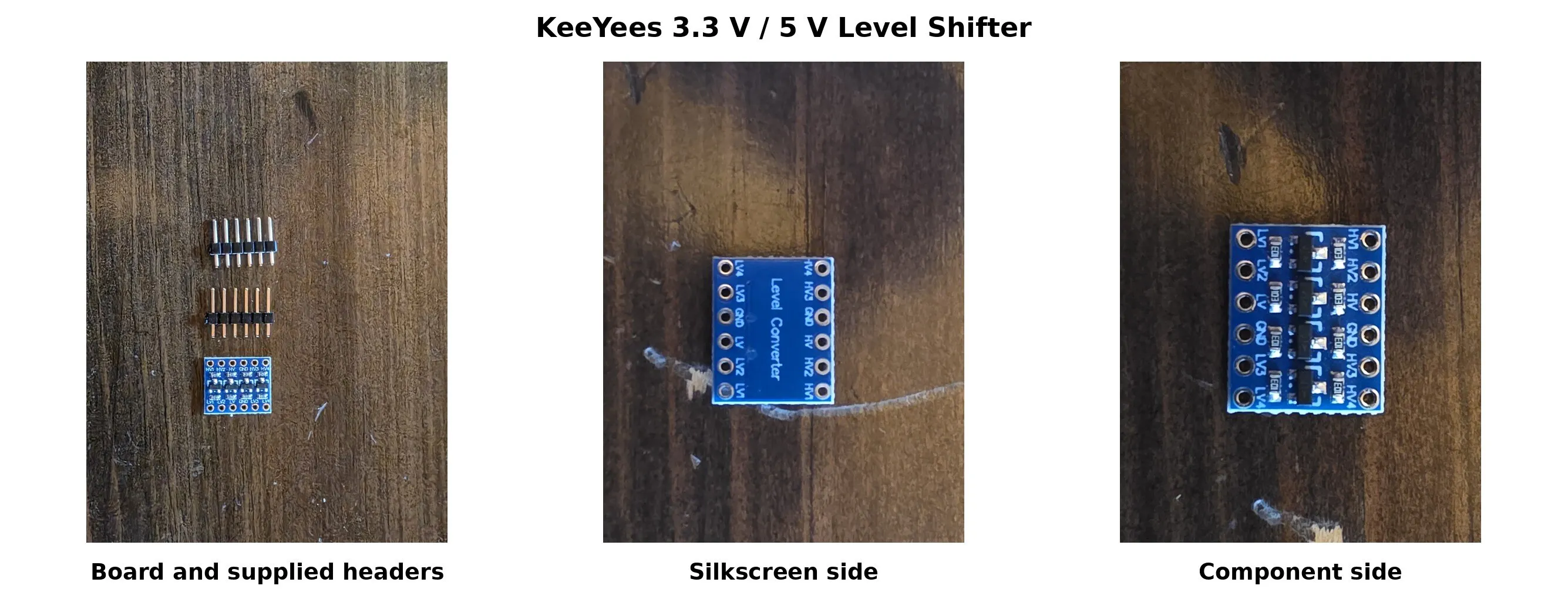
With power removed, I checked the board:
- The high- and low-side grounds were common.
- The supply rails were not shorted.
- Each numbered channel mapped to its partner.
- Each side had approximately 10 kΩ pull-ups.
- No obvious assembly defect was present.
The first live connection would use only two translated channels. The Atom would remain USB-powered, CN105 pin 3 would power only the level shifter’s 5-volt side, and the 12.48-volt pin 1 would remain isolated.
That arrangement let me test communication without tying the Atom’s USB 5-volt supply to the mini-split’s 5-volt supply.
The quiet serial line
Before attaching the controller, I watched the suspected indoor-unit transmit line with a battery-powered oscilloscope.
Nothing happened.
I turned the mini-split on with the physical remote, changed the temperature, changed modes, and turned it off again. The line remained essentially flat.
That initially raised several possibilities: the pin mapping might be wrong, the baud rate might be unexpected, or perhaps the unit did not transmit unless an accessory initiated the conversation.
The last explanation turned out to be correct.
The first conversation
For the controlled first connection, the AtomS3 Lite used GPIO1 as controller TX and GPIO2 as controller RX. ESPHome was configured for 2400 baud, eight data bits, even parity, and one stop bit.
The essential ESPHome configuration was surprisingly small:
logger:
  baud_rate: 0

uart:
  id: cn105_uart
  tx_pin: GPIO1
  rx_pin: GPIO2
  baud_rate: 2400
  data_bits: 8
  parity: EVEN
  stop_bits: 1

climate:
  - platform: mitsubishi_cn105
    name: Mitsubishi Mini Split
    uart_id: cn105_uart
    update_interval: 1s
    current_temperature_min_interval: 60s
    supported_swing_modes: BOTH
The first 2400-baud attempt worked.
As soon as the native ESPHome component began polling, the previously quiet indoor unit responded. The logs showed repeated controller requests and indoor-unit replies. Home Assistant received the mini-split’s actual operating state, target temperature, current room temperature, fan setting, and general vane state.
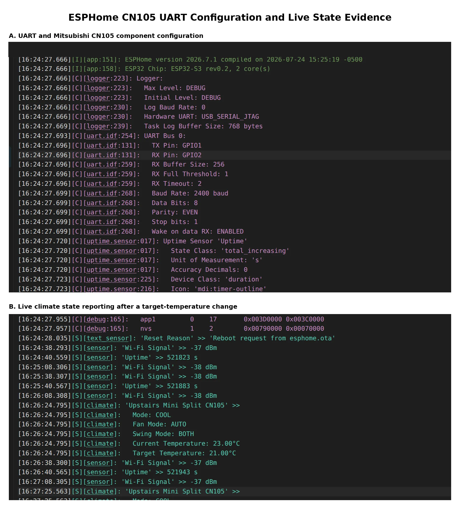
That was the point where the project stopped being a wiring experiment and became a real appliance integration.
Changes made with the physical SG15H remote appeared in Home Assistant in roughly 0.5 to 1 second. The controller also recovered cleanly after an ESPHome restart without changing the mini-split’s operating state.
Testing every control
After read-only validation, I tested commands one category at a time.
The native controller successfully handled:
- Power on and off.
- Heat.
- Cool.
- Auto/heat-cool.
- Dry.
- Fan-only operation.
- Target-temperature changes.
- Auto, quiet, low, medium, middle, and high fan settings.
- Vertical swing.
- Horizontal swing.
- Both swing directions.
- Swing off.
Returned CN105 state matched the observed physical behavior.
CN105 commands also have a pleasant operational difference from infrared commands: they are silent. The mini-split does not produce the acknowledgement beep associated with the physical IR remote.
A Natural Flow complication
One test briefly appeared inconsistent. Fan-speed commands were being accepted and reported correctly, but the physical airflow did not always behave as expected.
The cause was Mitsubishi’s Natural Flow feature, which had been enabled with the SG15H remote. Natural Flow alters airflow behavior outside the simple fan-mode abstraction exposed by the native ESPHome climate entity.
Once Natural Flow was disabled, fan response became deterministic.
That is worth remembering when validating a similar installation: disable Natural Flow with the physical remote before concluding that ordinary fan commands are not working.
The physical remote also exposes more specific fixed vane positions than the native Home Assistant interface. The ESPHome component provides the broader off, vertical, horizontal, and both swing categories. For this project, that was an acceptable limitation rather than a failed control path.
From prototype to appliance
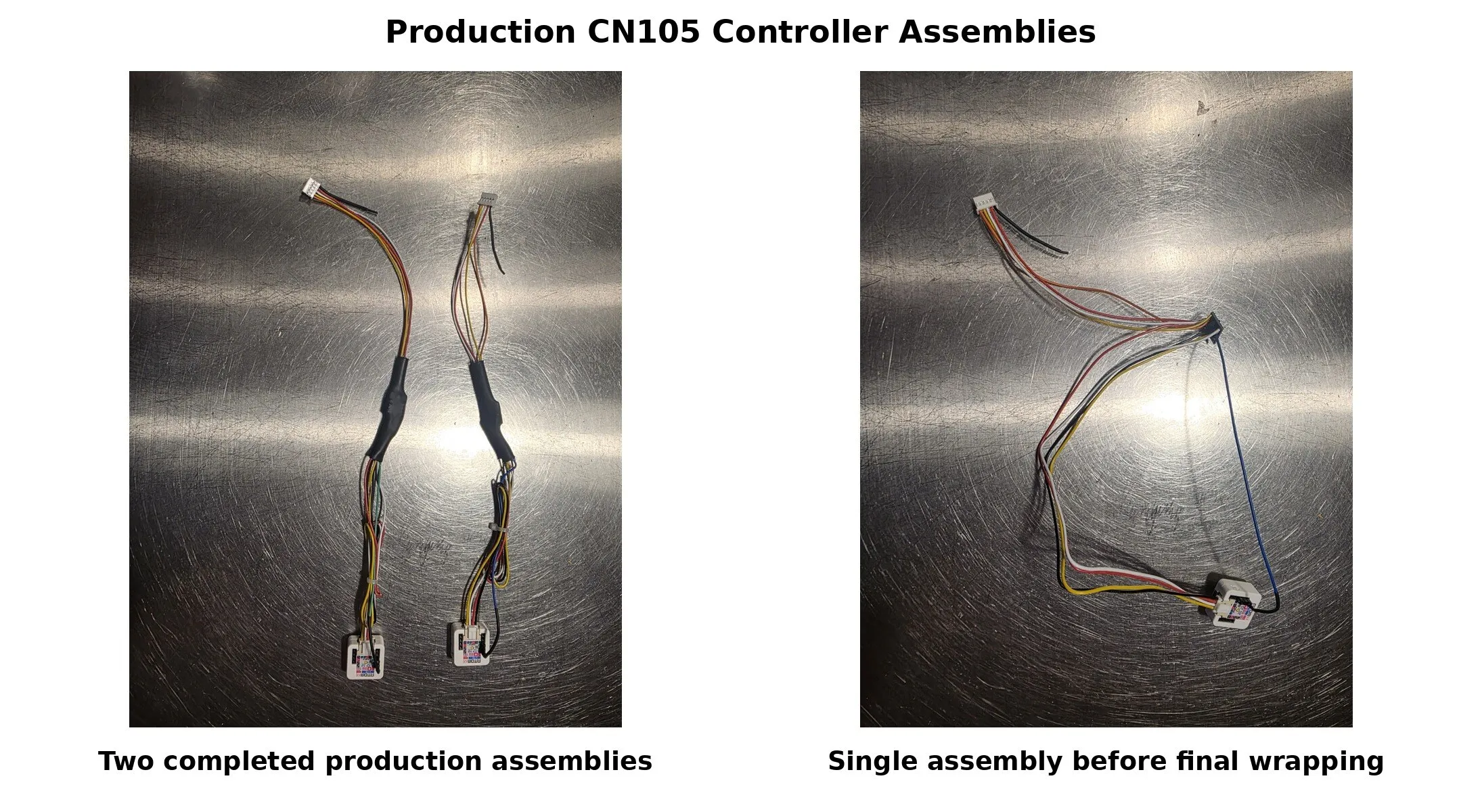
Once the temporary interface had passed read and write testing, I built two permanent assemblies.
Each production controller includes:
- A direct-soldered CN105 pigtail.
- A direct-soldered Grove cable to the AtomS3 Lite.
- A heat-shrink-wrapped level shifter.
- Individually insulated solder joints.
- A separately insulated and secured 12.48-volt pin-1 conductor.
- A stabilized connection from the Atom’s regulated 3.3-volt output to the level shifter’s low-voltage rail.
- Strain-managed wiring and removable CN105 connection.
The production wiring is:
| Signal | Connection |
|---|---|
| CN105 pin 1 / black | 12.48 V; insulated and unused |
| CN105 pin 2 / red | Common ground |
| CN105 pin 3 / white | Atom 5 V input and level-shifter HV rail |
| CN105 pin 4 / yellow | Indoor TX → HV1 → LV1 → Atom GPIO2/RX |
| CN105 pin 5 / orange | Atom GPIO1/TX → LV2 → HV2 → indoor RX |
Atom VDD_3V3 |
Level-shifter LV rail |
Both controllers are powered from CN105 during normal operation. They are installed in the protected low-voltage area of the indoor heads, clear of line-voltage conductors, moving parts, filters, condensate paths, and required airflow.
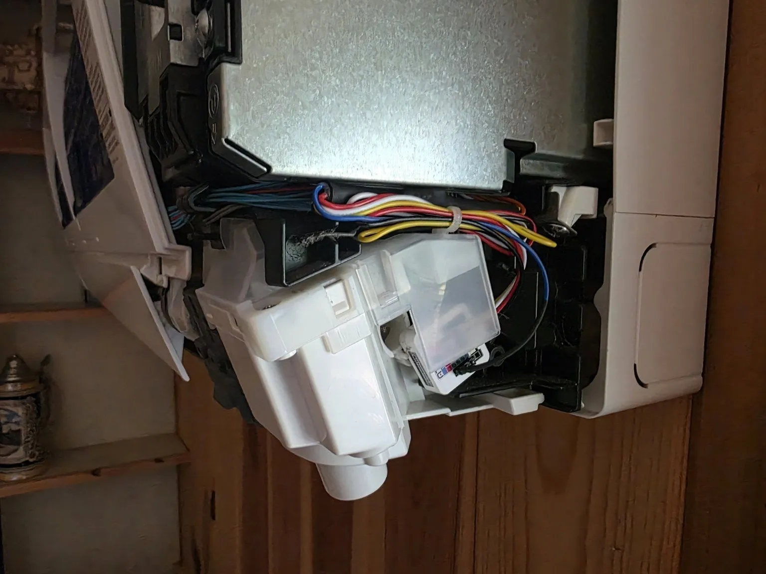
The installation remains reversible: unplug the CN105 pigtail from the Mitsubishi board and the indoor unit returns to its original configuration.
The USB rule
The Atom’s USB supply and the CN105 5-volt supply meet at the controller’s 5-volt input network. I do not connect USB while CN105 power is present.
The service procedure is:
1. Turn off the relevant mini-split breaker.
2. Confirm that the Atom has powered down.
3. Unplug CN105 from the Mitsubishi control board.
4. Verify that the controller is de-energized.
5. Connect USB and perform the required service.
6. Disconnect USB.
7. Reconnect CN105.
8. Restore the breaker.
Routine firmware maintenance uses ESPHome OTA and does not require opening the appliance.
Home Assistant as the authoritative control
The two installed CN105 climate entities are now the normal controls for the house.
The physical SG15H remotes still work, but their changes synchronize back through CN105. Home Assistant no longer has to guess what the appliance is doing. The Broadlink/SmartIR entities remain available under explicit fallback names, but normal dashboards and automations target CN105.
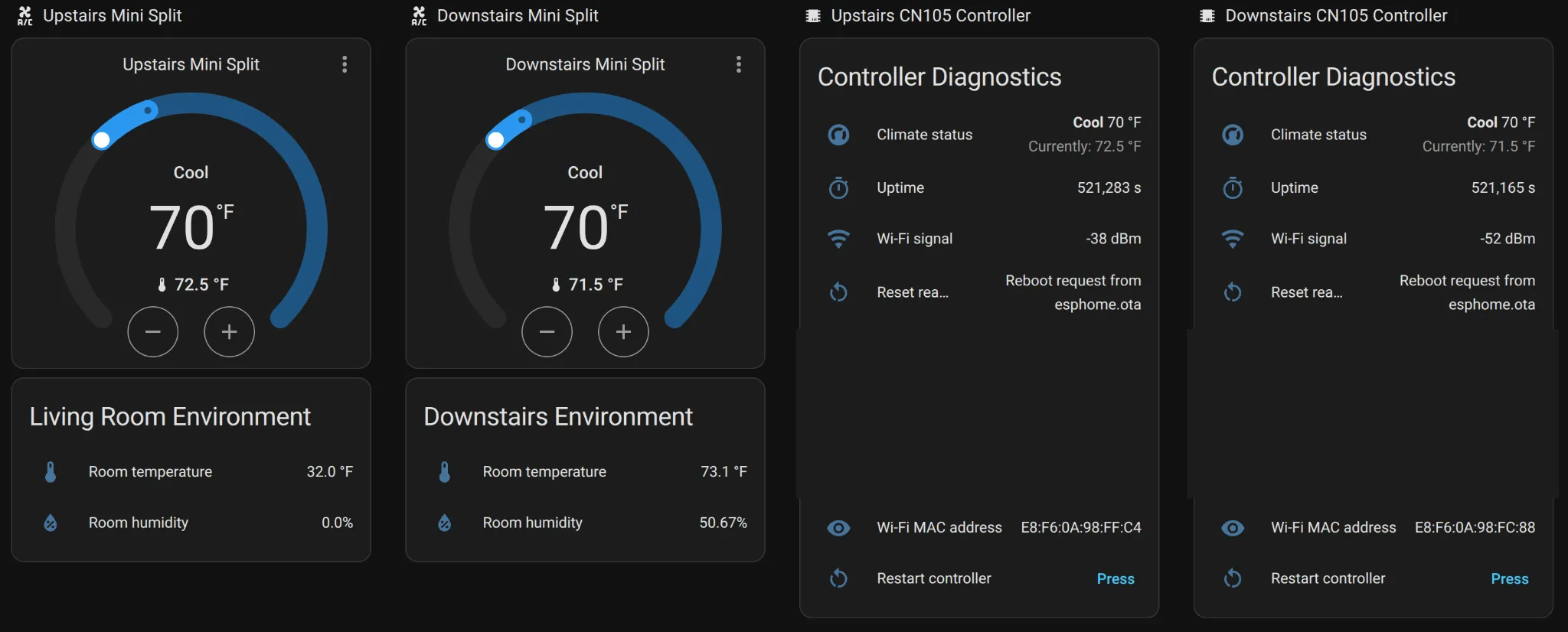
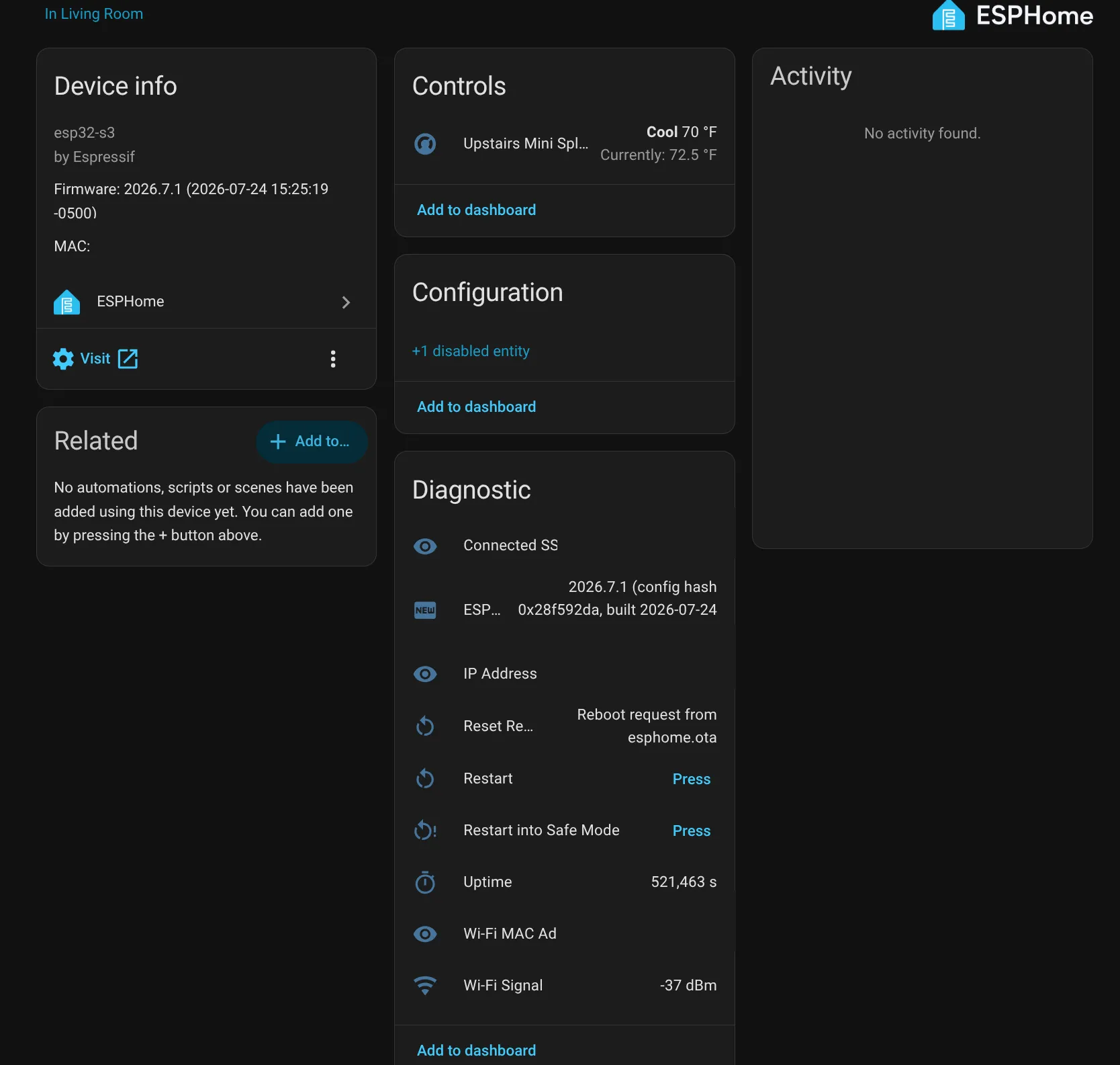
The controllers also report operational diagnostics including uptime, Wi-Fi signal, reset reason, ESPHome version, and availability. Frog Hill’s existing alert system watches for unavailable controllers, weak Wi-Fi, unexpected resets, and low room temperature.
Both controllers passed cold boot, ESPHome restart, and complete indoor-unit breaker-cycle testing. Neither issued an unexpected startup command.
Daily operation and reliability
The result feels appliance-like.
Commands are immediate. State reporting is authoritative. Changes from the physical remote appear in Home Assistant almost at once. The controllers require no cloud service and no special application beyond the Home Assistant and ESPHome systems already operating at Frog Hill.
Both production controllers were installed on July 23, 2026. As of July 30, 2026, they have been rock solid and 100% reliable in daily service.
During that first week I observed:
- No unavailable periods.
- No spontaneous controller resets.
- No missed commands.
- No state divergence.
- No protocol reconnect problems.
- No unexpected mini-split actions.
- No breaker-cycle recovery failures.
- No abnormal warming or other hardware concern.
A week is an encouraging result, not a seasonal reliability study. I plan to update this article after approximately one month, three months, six months, and one year of operation.
Before I rely on CN105 as the only control path for unattended winter-away protection, I also want meaningful cold-weather history and proven alert delivery. For now, CN105 is primary and authoritative, while SmartIR remains a clearly labeled fallback.
Reliability log
| Date | Time in service | Result |
|---|---|---|
| July 30, 2026 | 1 week | 100% reliable; no resets, outages, missed commands, divergence, or unexpected behavior |
| August 2026 | 1 month | Planned update |
| October 2026 | 3 months | Planned update |
| January 2027 | 6 months | Planned update |
| July 2027 | 1 year | Planned update |
What this project changed
This project began because the available control paths were unsatisfying.
The official kumo cloud devices never became operational here. Broadlink infrared control worked, but it could not provide authoritative state. CN105 offered a third path: direct local communication with the appliance.
The native ESPHome component made that path practical, but the successful result still depended on treating the actual hardware as evidence.
The most valuable finding was not that 2400-baud serial communication worked. It was that a pin documented generically as unconnected carried 12.48 volts on these units. Measuring first turned a potentially destructive assumption into a safe, repeatable installation.
That is the kind of system I want Frog Hill Labs to produce:
- Local where practical.
- Understandable.
- Measured rather than assumed.
- Reversible.
- Monitored.
- Documented well enough to repair later.
- Honest about what has and has not yet been proven.
The Mitsubishi mini-splits were already good appliances. CN105 finally gave them a control system to match.
Additional reference views
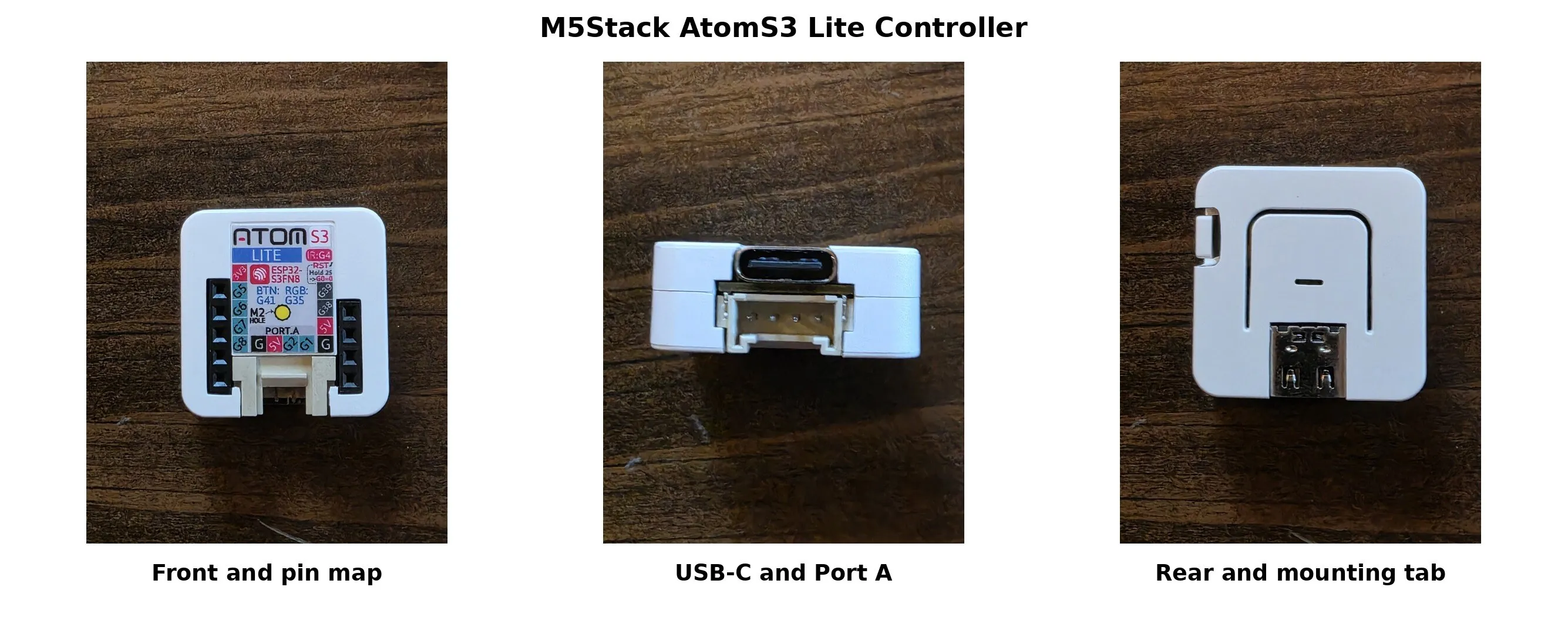
Build reference
Major parts
| Quantity | Part | Purpose |
|---|---|---|
| 2 | M5Stack AtomS3 Lite | Installed ESPHome controllers |
| 1 | M5Stack AtomS3 Lite | Bench/reference controller |
| 2 | PAP-05V-S/JST PA-style five-wire pigtails | CN105 connection |
| 2 | KeeYees four-channel 3.3 V/5 V level shifters | UART voltage-domain interface |
| 2 | Grove/HY2.0-4P cables | Atom Port A connection |
| — | Heat shrink, wire, header pins, zip ties | Insulation, connection, and strain management |
Proven Frog Hill configuration
Indoor units: Mitsubishi MSZ-FH12NA
Physical remote: Mitsubishi SG15H
Controller: M5Stack AtomS3 Lite
ESPHome component: mitsubishi_cn105
UART: 2400 baud, 8 data bits, even parity, 1 stop bit
Controller TX: GPIO1
Controller RX: GPIO2
State polling: 1 second
Current-temperature minimum interval: 60 seconds
Safety boundary
The indoor heads contain 208/230-volt circuitry.
- Turn off the breaker before opening a head or inserting/removing CN105.
- Do not probe or modify line-voltage circuitry.
- Verify the actual connector orientation, continuity, and voltage levels.
- Do not assume pin 1 is unconnected.
- On the Frog Hill units, pin 1 measured 12.48 volts and remains insulated and unused.
- Do not connect USB while CN105 power is present.
- Keep installed hardware clear of moving parts, filters, condensate, airflow, and line-voltage wiring.
- Do not use this article as a substitute for competent electrical judgment.